A single pole transfer function has the general from of
\[ H(s) = \dfrac{1}{1 + \frac{s}{p}} \]
Since H(s) has no roots in the numerator, the transfer function H(s) has no zeros. H(s) does have one root in the denominator, at
\[ s = -p \]
H(s) is said to have one pole at -p in the left-hand plane. As will be seen in the following sections, there are some important attributes for the magnitude and phase of a transfer function which can be generalized around the pole location.
From complex number theory the magnitude-squared of a function can be related as
\[ \left| H(s) \right|^2 = H(s) \cdot H^*(s) \]
For \( s = j\omega \)
where the astrix is the complex conjugate of H
\[ H^*(j\omega) = H(-j\omega) \]
\begin{align*}
\left| H(j\omega) \right| ^2 &= H(j\omega)H(-j\omega) \\
&= \left( \dfrac{1}{1 + \frac{j\omega}{p}} \right)\left( \dfrac{1}{1 + \frac{-j\omega}{p}} \right) \\
\left| H(j\omega) \right| ^2 &= \dfrac{1}{1 + \frac{\omega^2}{p^2} }
\end{align*}
When \( \omega = p \), \( \left| H(j\omega) \right| ^2 = 1/2 \)
Finally the magnitude of H(jw) then becomes
\[ |H(j\omega)| = \dfrac{1}{\sqrt{1 + \frac{\omega^2}{p^2} }} \]
The phase response of H(jw) is related by the real and imaginary components of H(jw) as follows
\[ \angle H(j\omega) = arg\left( H(j\omega )\right) = tan^{-1}\left( \dfrac{\mathbb{I}\left( H(j\omega) \right)}{\mathbb{R}\left( H(j\omega) \right)} \right) \]
Normalizing H(jw) into the form \(a + jb\) is as follows
\begin{align*}
H(j\omega) &= \dfrac{1}{1 + \frac{j\omega}{p}}\\
&= \left(\dfrac{1}{1 + \frac{j\omega}{p}}\right) \left( \dfrac{1 – \frac{j\omega}{p}}{1 – \frac{j\omega}{p}} \right)\\
H(j\omega)&= \dfrac{1}{1 + \frac{\omega^2}{p^2}} – j\left( \dfrac{\omega/p}{1 + \frac{\omega^2}{p^2}} \right)
\end{align*}
The real component is
\[ \mathbb{R}\left( H(j\omega) \right) = \dfrac{1}{1 + \frac{\omega^2}{p^2}} \]
The imaginary component is
\[ \mathbb{I}\left( H(j\omega) \right) = \dfrac{-\omega/p}{1 + \frac{\omega^2}{p^2}} \]
The phase of H(jw) is then
\[ \angle H(j\omega) = tan^{-1} \left( \dfrac{\omega}{p} \right) \]
It’s worth illustrating that the reason the phase sweeps near the pole P is due to the fact that the real component declines at \(1/\omega^2\), where as the imaginary component declines slower at \( 1/\omega \).
\begin{align*}
| H(j\omega)| &= \sqrt{\left(\mathbb{R}\left( H(j\omega) \right)\right)^2 + \left(\mathbb{I}\left( H(j\omega) \right)\right)^2 } \\
&= \sqrt{\left( \dfrac{1}{1 + \frac{\omega^2}{p^2}} \right)^2+\left( \dfrac{\omega/p}{1 + \frac{\omega^2}{p^2}}\right)^2} \\
&= \sqrt{\dfrac{1 + \frac{\omega^2}{p^2}}{\left(1 + \frac{\omega^2}{p^2} \right)^2}} \\
| H(j\omega)| &=\dfrac{1}{\sqrt{1 + \frac{\omega^2}{p^2} }}
\end{align*}
The magnitude of H computed from the real and imaginary components is equivalent to the square root of the magnitude-squared relation.
\[ | H(j\omega)| = \sqrt{H(j\omega)H(-j\omega)} \]
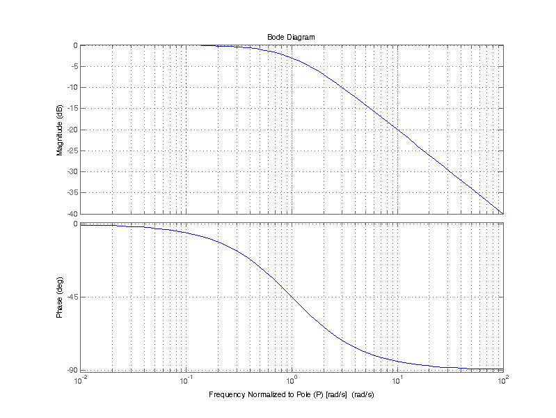
The figure below is a bode plot of a the single pole transfer function H(s). Frequency \( \omega \) is normalized to pole P, i.e. the ratio \( \omega/P\) is plotted on the x-axis. The top half of the plot depicts the magnitude, the bottom half the phase. Magnitude is plotted on a 20log10 dB scale.

There are a few important attributes for magnitude and phase of H(jw) near the pole P. The magnitude is left unperturbed from its DC value, in this case unity or 0 dB, up until omega equals P. When \(\omega = P\), the magnitude “breaks” at -20 dB/decade, and continue indefinitely. The phase of H(jw) begin to decline at 0.1 P up until 10 P, at a rate of -45 deg/decade.
The table below provides the exact evaluation of H(jw) at some normalized frequencies before and after the Pole P.
| Normalized Frequency (w/p) | Real(H(jw)) | Imag(H(jw)) | Magnitude (dB) | Phase (deg) |
|---|---|---|---|---|
| 0.01 | 0.9999 | 0.0100 | -0.0004 | -0.6 |
| 0.1 | 0.9901 | 0.0990 | -0.0432 | -5.7 |
| 1 | 0.5000 | 0.5000 | -3.0103 | -45.0 |
| 10 | 0.0099 | 0.0990 | -20.0432 | -84.3 |
| 100 | 0.0001 | 0.0100 | -40.0004 | -89.4 |
A single pole transfer function may also be described as a low-pass filter. Where the passband (the signals of interest) is from DC up until when \(\omega_c=2\pi f_c = P\). Beyond the corner frequency signals are rejected (attenuated). However in the case of a single pole filter, a signal at frequency of 2*fc is only attenuated by 0.45 or -7 dB. It isn’t until frequencies of 10x or 100x fc that the attenuation becomes -20 dB or -40 dB respectively.
When attenuation of much greater than a few dB is desired just after the corner frequency (i.e a sharp roll-off) a higher order filter is required.
Excellent explanation!