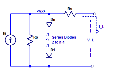
A solar panel is constructed as a series string of discrete solar cells (or potentially parallel array). Each cell of the series string has its own series resistance and shunt resistance in addition to the diode junction. Loosely speaking one can construct a circuit equivalent model of a solar panel as shown in the figure below.

Here the panel is constructed with N equal diode junctions all sharing one common photo current source \(I_S\).
We can attempt to solve the load I-V relationship by either applying a know voltage source \(V_L\) or apply a know load current \(I_L\) and then proceed to solve the available load current or load voltage. In this blog post we will apply a know load voltage \(V_L\) and solve for the available load current \(I_L\).
We begin naming the internal voltage across the series string of diodes node \(V_X\). We then apply KCL at \(V_X\) as,
$$ -I_S + \dfrac{V_X}{R_P} + I_o \exp(\dfrac{Vx}{N\eta V_T}) + \dfrac{V_X-V_L}{R_S} = 0$$
Solution of the above equation requires use of the lambert-w function and is far from trivial. We may also solve the equation numerically in Matlab. Sample Matlab code is shown below,
% Define anonymous function based on KCL at internal node Vx
f = @(Vx) (Vx-VL)/Rs + Io*exp(Vx/(N*eta*VT)) + Vx/Rp - Is;

% solve first root
Vx = fzero(f,[min(0,VL) 1*eta*N]);

% Output Load Current
IL = (Vx - VL)/Rs;
Simulation Example
Suppose we wish to determine the impact of panel series resistance on the available output power. In the sample code below we define panel parameters and solve for the available load current for some load voltage \(V_L\) and panel series resistance \(R_S\). For simplicity the iteration of panel voltage and series resistance is omitted.
k   = 1.3806e-23;
q   = 1.602e-19;
Is  = 0.1;
N   = 4;
Io  = 1e-10;
eta = 2;
T   = 300;
VT  = k*T/q;
Rp  = 100e3;
Rs  = 1e-3;

% Define anonymous function based on KCL at internal node Vx
f = @(Vx) (Vx-VL)/Rs + Io*exp(Vx/(N*eta*VT)) + Vx/Rp - Is;

% Solve first root
Vxi = fzero(f,[min(0,VL) 1*eta*N]);

% Output Load Current
IL = (Vxi - VL)/Rs;
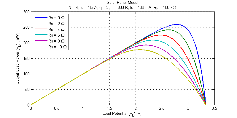
The results from the simulation code above are shown in the figure below.

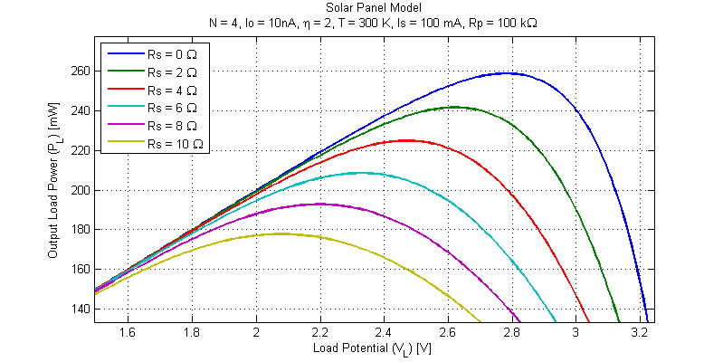
We can first note that the panel open-circuit voltage is unaffected by series resistance (this makes sense as with no load current there is no voltage drop across the series resistance \(R_S\)). A second plot focusing on the MMP of the various simulation runs is shown in the figure below.

The maximum point for each simulation run is shown in the table below.
| Rs [Ohms] | Pmax [mW] | Vp [V] | Ip [mA] | Vx [V] |
|---|---|---|---|---|
| 0 | 259 | 2.78 | 93.0 | 2.78 |
| 2 | 242 | 2.62 | 92.1 | 2.81 |
| 4 | 225 | 2.47 | 91.0 | 2.83 |
| 6 | 209 | 2.33 | 89.6 | 2.87 |
| 8 | 193 | 2.20 | 87.8 | 2.90 |
| 10 | 178 | 2.08 | 85.5 | 2.93 |
We can observe that to a first order the decline in output power is approximately equal to the \(I^2R\) losses of the series resistor \(R_S\).
Wow!! Amazing blog. you are really a great writer. your solar panel procedure is really great. Solar panel installation is important for saving money and the environment.