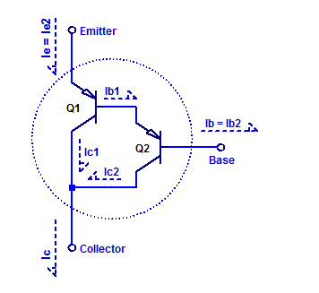
The darlington transistor arrangement consists of 2 cascaded bipolar transistors, in such a manor that the forward current gain of the first transistor is multiplied by the second. A schematic of a PNP darlington transistor arrangement is shown in the figure below.

The dashed outline depicts the formation of one supper-beta pnp transistor. We can note that transistor Q2 is a pre-driver to transistor Q1. To asses the complete forward dc current gain of the darlington pair, we begin by apply KCL at each of the terminals as,
$$ I_C = I_{C1} + I_{C2} $$
$$ I_E = I_{E1} $$
$$ I_B = I_{B2} $$
The forward current gain of the darlington arrangement is then,
\begin{align*}
\beta &= \dfrac{I_C}{I_B} \\
&= \dfrac{I_{C1}+I_{C2}}{I_{B2}} \\
&= \dfrac{\beta_1 I_{B1}+ \beta_2 I_{B2}}{I_{B2}} \\
&= \dfrac{\beta_1 I_{E2}+ \beta_2 I_{B2}}{I_{B2}} \\
\end{align*}
The emitter current of Q2 is,
$$ I_{E2} = I_{B2} + \beta_2 I_{B2} = (1+\beta_2)I_{B2} $$
Substitution back into the beta relation yields,
\begin{align*}
\beta &= \dfrac{\beta_1 (1+\beta_2) I_{B2} + \beta_2 I_{B2}}{I_{B2}} \\
\beta &= \beta_1\beta_2 + \beta_1 + \beta_2 \\
\end{align*}
For \( \beta_1 >> 1\) and \( \beta_2 >> 1\) the forward DC current gain simplifies to,
$$ \beta \simeq \beta_1 \beta_2 $$
Hence, the darlington pair behaves just like a single bipolar transistor with the relation,
$$ I_C = \beta I_B $$
Measurement Setup
A sample darlington transistor arrangement is constructed with an MPS4250 as a pre-driver and a MJE15029 power transistor. The relevant component specifications are as follows,
MPS4250: \(\beta = 450\), \(V_{cemax} = 40 \text{VDC}\)
MJE15029: \(\beta = 150\), \(V_{cemax} = 120 \text{VDC}\)
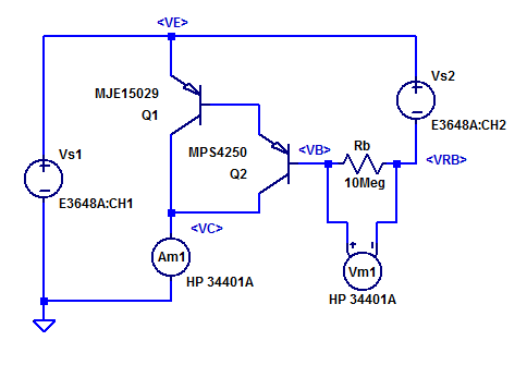
A schematic of the test setup is shown in the figure below.

Transistors Q1 and Q2 form a darlington transistor, whose emitter potential is referenced to bench power supply \(V_S1\). A base current is developed by biasing a series resistor \(R_B\) at a potential below \(V_E\) by bench supply \(V_{s2}\). Since the base current is expected to be below one 1 uA, base current is measured by also employing bias resistor \(R_B\) as a current shunt resistor. The base current shunt is sampled by voltmeter \(V_m1\) while being configured for hi-z input impedance.
Ammeter \(A_{m1}\) employs an internal 5 \(\Omega\) current shunt resistor for 10 mA and 100 mA measurement scales. The potential at \(V_C\) is then,
$$ V_C = R_{Am1} I_C = 5 I_C $$
At a full scale test current of 100 mA, \(V_C\) rises to 500 mV and consequently the DUT’s \(V_{CE}\) declines to,
$$ V_{CE} = V_C – V_E = -V_{s1} + 5I_C$$
Bench supply \(V_{s2}\) is programmaticly stepped from 0 to 12 VDC, which in turn steps the base current from 0 nA to approx 1 uA. With the exact figure determined by voltmeter \(V_{m1}\). The resulting collector current is sampled by ammeter \(A_{m1}\). The process is repeated for 4 \(V_{CE}\) bias voltages.
Measurement Results
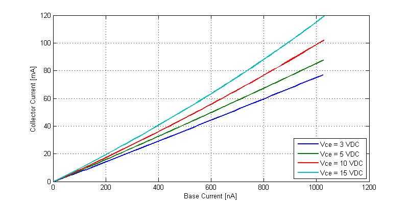
The base and collector currents for 4 {V_CE} bias runs is shown in the figure below.

Approximately speaking, with a 1 uA base current the collector current ranges from 70 mA to 120 mA, depending on \(V_{CE}\) and junction temperature.
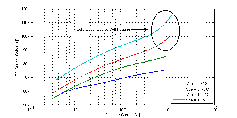
A plot of the forward current gain \(\beta\) versus collector current is shown in the figure below.

We can note that the current gain is a function of \(I_C\), \(V_{CE}\), and \(T_J\).