In this post, the maximum power point (MPP) of a diode shunted current source will be assessed and modeled. A solar cell in its simplest description is merely a semiconductor diode. When the cell’s junction is illuminated, a photo current \(Is\) is produced. A basic schematic model of an ideal solar cell is shown in the figure below.
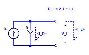
For diode forward voltages \(V_D\) greater than a few \( \eta V_T\), such as 100 mV, the diode equation is approximately equal to,
$$ I_D \simeq I_o exp\left( \dfrac{V_D}{\eta V_T} \right) $$
Applying KCL at the output node of the schematic above yields,
$$ I_D + I_L = I_S $$
$$ I_D = I_S – I_L $$
The forward voltage of the diode can be determined as,
\begin{align*}
V_D &= \ln \left( \dfrac{I_D}{I_o} \right) \eta V_T \\
V_D &= \ln (I_S – I_L)\eta V_T -\ln (I_o)\eta V_T
\end{align*}
The output load power is equal to,
$$ P_L = V_L \cdot I_L $$
Since the output terminals are in parallel to the shunt diode’s terminals the output load voltage is identical to the diode’s forward voltage,
$$ V_L = V_D $$
Hence, the output load power as a function of load current becomes,
$$ P_L = \ln( I_S – I_L )\eta V_T I_L – \ln(I_o)\eta V_T I_L $$
Differentiating the load power with respect to load current yields,
$$ \dfrac{\partial P_L}{\partial I_L} = \dfrac{\eta V_TI_L(-1)}{I_S-I_L} + \ln(I_S-I_L)\eta V_T – \ln(I_o)\eta V_T $$
We can determine the MPP as the the inflection point where \(\partial P_L/\partial I_L\) equals 0, as,
\begin{align*}
\left| \dfrac{\partial P_L}{\partial I_L} \right|_{I_L=I_P} &= 0 \\
\ln \left( \dfrac{I_S – I_P}{I_o} \right)\eta V_T &= \dfrac{ I_P \eta V_T}{I_S – I_P} \\
\end{align*}
We then arrive at the following expression for the MPP load current,
$$\ln \left( \dfrac{I_S – I_P}{I_o} \right) = \dfrac{I_P}{I_S – I_P} \tag{EQ.1} $$
The solution for the load current \(I_L\) which yields the maximum output load power is only a function of the current source \(I_S\) and the diode’s saturation current \(I_o\). The solution of \(\ln(ax)=bx+c\) is non-trivial. Hence, we will attempt to find an approximation for the natural log function. A plot left-hand term of EQ.1 is shown in the figure below.
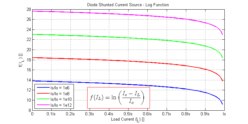
Here to simplify the solution we will begin by assuming the maximum power point occurs at 0.9 I_s (10% less than a short circuit condition). The natural logarithm can then be approximated as,
$$ \ln \left( \dfrac{I_S – 0.9I_S}{I_o} \right) = \ln \left( \dfrac{0.1I_S}{I_o} \right) $$
Substitution our approximated log term yields,
$$ \ln \left( \dfrac{0.1I_S}{I_o} \right) = \dfrac{ I_P}{I_S – I_P} $$
The approximate MPP load current is then,
$$ I_P = I_S\left( \dfrac{\ln(0.1I_S/I_o)}{1+\ln(0.1I_S/I_o)} \right) $$
The table below provides the approximate MMP load current for a diverse range of source currents \(I_S\) and diode saturation currents \(I_o\).
| \(I_S/I_o\) | MPP Current \(I_P\) |
|---|---|
| \(10^6\) | \(0.920 I_S\) |
| \(10^7\) | \(0.933 I_S\) |
| \(10^8\) | \(0.942 I_S\) |
| \(10^9\) | \(0.949 I_S\) |
| \(10^{10}\) | \(0.954 I_S\) |
| \(10^{11}\) | \(0.958 I_S\) |
| \(10^{12}\) | \(0.962 I_S\) |
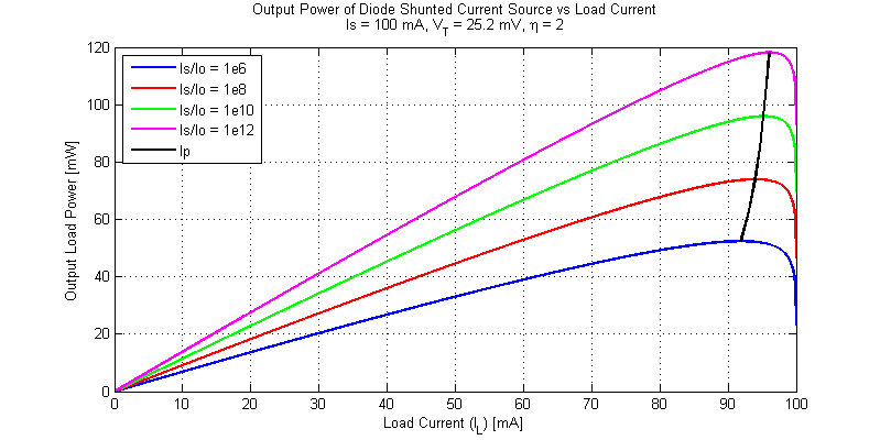
The output power of a diode shunted current for an assortment of load and source conditions is shown in the figure below.
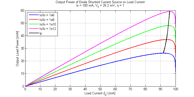
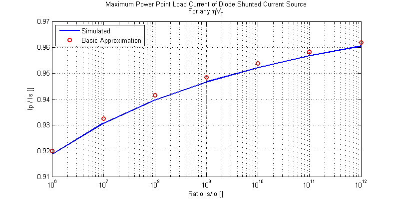
Even when the ratio \(I_S/I_o\) varies by over 6 orders of magnitude the MPP load current is only perturbed from \(0.919I_S\) to \(0.961I_S\).
A plot for diode ideality factor \(\eta = 2\) is shown in the figure below.
As shown in the analysis above, the MPP load current is not a function of \(V_T\) or \( \eta \).
Solar Perspective
The fill factor of a solar cell is defined as,
$$ FF = \dfrac{V_{mp}I_{mp}}{V_{oc}I_{sc}} $$
We have seen that for a diode shunted current source the MPP load current is roughly 92% to 96% of the short-circuit current. Hence the ratio \(I_{mp}/I_{sc}\) is known and relatively constant over a diverse range of illumination currents and junction saturation currents.
During open-circuit conditions, all of the generated photo current is conducted by the shunt diode. At the maximum power point the conducted current through the diode declines to 4% to 8% of the short-circuit current (the rest of the photo current is delivered to the load). We can solve the decline in forward voltage as,
$$ \Delta V_D = \eta V_T \ln\left( \dfrac{I_S}{I_S – I_P} \right) $$
As an illustration consider,
$$ \eta = 1, \;\;\; V_T = 25.2 \text{ mV},\;\;\; I_S = 100 \text{ mA}, \;\;\;I_o = 100 \text{ pA}$$
The MPP load current is then approximately,
$$ I_P \simeq 0.95 I_S $$
$$ \Delta V_D = 25.2 \ln( 1/0.05 ) = 25.2 \ln(20) = 75.5 \text{mV} $$
The current source’s open circuit voltage is,
$$ V_{oc} = 25.2 \ln( 100 \text{ mA} / 100 \text{ pA} ) = 522.2 \text{ mV} $$
$$ V_{mp} = 25.2 \ln( I_D / 100 \text{ pA}) = 25.2\ln(5 \text{ mA}/100 \text{ pA}) = 446.7 \text{ mV} $$
Finally we can determine the fill factor for this example as,
$$ FF = \dfrac{(446.7)(0.95)}{(552.1)(1)} = 0.812 $$
$$ P_{max} = (0.812)V_{oc}I_{sc} $$
The take away from all of this, is, that the load current for maximum output power is approximately equal to 95% of the short-circuit current. Since the ratio of \(I_{mp}/I_{sc}\) is approximately constant, the decline in output voltage \(\Delta V\) from \(V_{oc}\) to \(V_{mp}\) is also a constant number of \( (\eta V_T) \) ‘s.
One could loosely approximate the fill factor of a single solar cell as,
$$ FF \simeq \left(\dfrac{V_{oc} – 75\text{ mV}}{V_{oc}}\right) (0.95) $$
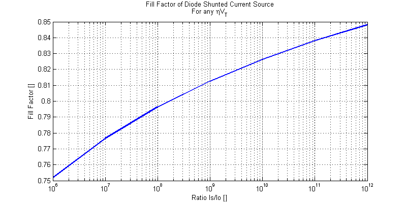
Which clearly indicates that the larger the open circuit voltage (either by larger photo current or by a smaller saturation current) the higher the fill factor. A plot of fill factor for a wide range of photo and diode saturation currents is shown in the figure below.
