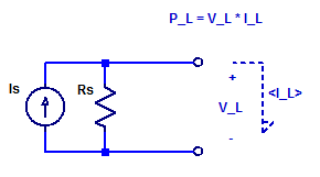
While it is true an ideal current source can deliver an infinite amount of output power (at a constant current), as the output compliance voltage is infinite. A real current source has a finite output resistance which limits the maximum output voltage that can be developed across the current source. To asses the peak output power of a current source, we will develop a relation for the output voltage as a function of load current. Consider the schematic of a current source connected to some arbitrary load \(V_L\) & \(I_L\).

KCL across the output nodes of the current source yields,
$$ \dfrac{V_L}{R_s} + I_o = I_s $$
$$ V_L = \left( I_s – I_o \right) R_s $$
The power consumed by the load is then simply the current-voltage product as,
\begin{align*}
P_L &= V_L I_L \\
&= \left( I_s – I_L \right) R_s I_L \\
&= R_s \left( I_sI_L – I_L^2 \right) \\
\end{align*}
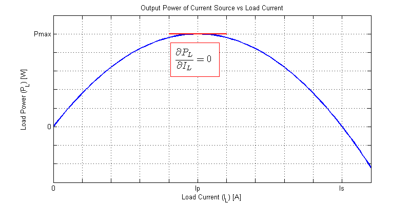
The output power is a 2nd order function of load current. A normalized graph of load power versus load current when powered by a current source is shown in the figure below.

At some load current \(I_P\) the output power reaches its maximal value and then begins to decline. We can solve for the maximum power point \(P_{max}\) as the point where the first derivative of \(P_L(I_L)\) equals 0.
$$ \dfrac{\partial P_L}{\partial I_L} = I_sR_s -2R_sI_L $$
\begin{align*}
\left| \dfrac{\partial P_L}{\partial I_L} \right|_{I_L=I_P} &= 0\\\\
0 &= I_sRs – 2R_sI_P \\\\
I_P &= \dfrac{I_s}{2} \\\\
\end{align*}
Hence, the maximum load power occurs when the load current equals \( I_s/2\).
It should come as no surprise that a resistive load which consumes the maximum available power is a resistor of \(R_L = R_S\).
The maximum available power is then,
\begin{align*}
P_{max} &= P_L( I_P )\\
&= R_s( I_sI_P – I_P^2 )\\
&= R_s( \dfrac{I_s^2}{2} – \dfrac{I_s^2}{4} )\\
P_{max} &= \dfrac{I_s^2R_s}{4} \\
\end{align*}
Spice Example
Consider a current source with the following parameters,
$$ I_s = 100 \text{ [mA]}\;,\;\;\; R_s = 100 \; [\Omega] $$
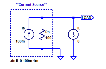
A sample spice test jig is shown in the figure below.

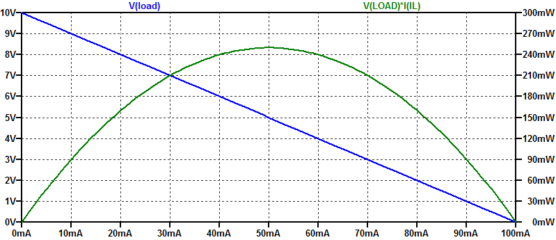
Ideal current source \(I_s\) and shunt resistance \(R_s\) form a current source with output resistance \(R_S\). An ideal current source is parametricly swept from \(0\) mA to \(100\) mA as a synthetic load. The results of the simulation are shown in the figure below.

The open-circuit voltage of the current source is \(V_{oc} = I_s R_S = 10 \) VDC. the short-circuit current is \( I_{sc} = I_s = 100 \) mA. The maximum power point occurs at a load current of \(50\) mA, with a corresponding peak load power of \(250\) mW.
The maximum power point as estimated from the analysis above occurs at a load current of,
$$ I_P = \dfrac{I_s}{2} = 50 \text{ [mA]} $$
With a maximum power point of,
$$ P_{max} = \dfrac{I_s^2R_s}{4} = 250 \text{ [mW]} $$
Solar Perspective
If a solar cell were to appear as a current source with shunt resistance \(R_S\) then its short-circuit current is simply,
$$ I_{SC} = I_S $$
The cells open circuit voltage is,
$$ V_{OC} = I_S R_S $$
The maximum power available from the cell would be,
$$ P_{max} = \dfrac{I_s^2R_s}{4} = \dfrac{V_{OC}I_{SC}}{4} $$
Hence a current source with shunt resistance has a fill factor of 0.25.