The banner line description of the BUK9535 power MOSFET is given as,
Logic level N-channel enhancement mode Field-Effect Transistor (FET) in a plastic package using TrenchMOS technology
In the sub-threshold region we can fit the drain current to the following basic exponential model,
$$ I_D =I_S \exp\left( \dfrac{V_{GS}}{\eta V_T}\right) $$
Measurement Setup
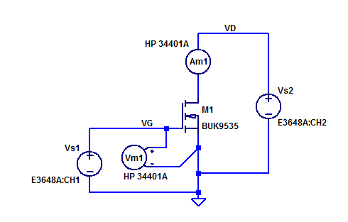
Bench supply \(V_{s1}\) provides the gate-source bias potential \(V_{GS}\). Voltmeter \(V_{m1}\) records the effective gate-source potential at the terminals of \(M_1\). Bench supply \(V_{s2}\) biases the drain of \(M_1\) at \(\simeq 5\) VDC. With \(V_D\) = 5, \(M_1\) is biased into the saturation region for a diverse range of gate drive potentials. A schematic of the test setup is shown in the figure below.

Ammeter \(A_{m1}\) will present a small burden voltage in series with supply \(V_{s1}\). \(A_{m1}\) employs a \(5\Omega\) current shunt resistor for its \( 10 \& 100 \) mA current ranges. Worst case burden in the sub-threshold region is,
$$ V_{BRD} = (0.1)(5) = 500 \text{ mV} $$
With a 100 mA of drain current the drain potential will decline from 5V to 4.5V a 10% reduction in drain bias. Fortunately \( M_1\) has a modest \( \lambda \) in the sub-threshold region.
Measurement Results
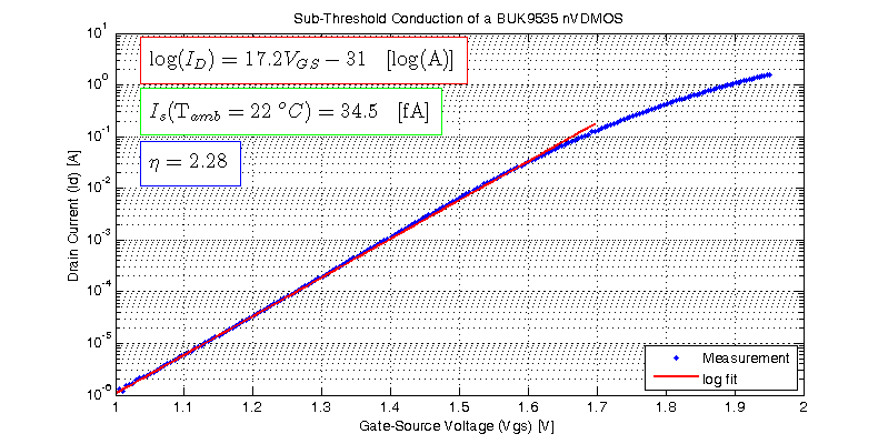
The results of sweeping \(V_{GS}\) of a sample DUT at a fixed \(V_{DS}\) of 5 V is shown in the figure below.

The log fit results in the following exponential function of \(V_{GS}\),
$$ I_D =34.5\text{ fA } \exp\left( \dfrac{V_{GS}}{58 \text{ mV}}\right) $$
Every 10x increase in drain current in the sub-threshold region requires an additional gate drive voltage of,
$$ \Delta V_{GS} = \eta V_T \log(10) = 134 \text{ mV/dec} $$
HI