Raspberry Pi Pico

I am going to publish all my RPI Pico adventures on pages versus blogs posts in an attempt to maintain some continuity in this blog. The style of these pages will be far more conversation and from the perspective of a total beginner to the Pico & \(\mu\text{Python}\). So all the Pico content will be indexed through this blog post versus the main site page.

My Experiences

On the Road to Blinky

Burning Questions

These are questions I had about the Pico before ever using one. Since getting my hands on one 🙂 I am starting to answer these questions below. Each page lists 5 questions with an answer that is as straightforward as I can author (LOL).

Questions & Answers 1-5

Continue reading “Raspberry Pi Pico”
Sub-Threshold Conduction of a Power MOSFET

The banner line description of the BUK9535 power MOSFET is given as,

Logic level N-channel enhancement mode Field-Effect Transistor (FET) in a plastic package using TrenchMOS technology

In the sub-threshold region we can fit the drain current to the following basic exponential model,

$$ I_D =I_S \exp\left( \dfrac{V_{GS}}{\eta V_T}\right) $$

Continue reading “Sub-Threshold Conduction of a Power MOSFET”

Basic Solar Panel Model

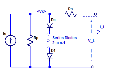
A solar panel is constructed as a series string of discrete solar cells (or potentially parallel array). Each cell of the series string has its own series resistance and shunt resistance in addition to the diode junction. Loosely speaking one can construct a circuit equivalent model of a solar panel as shown in the figure below.
Simplified Schematic of an N Cell Solar Panel.

Here the panel is constructed with N equal diode junctions all sharing one common photo current source \(I_S\). Continue reading “Basic Solar Panel Model”

Maximum Power Point of Diode Shunted Current Source

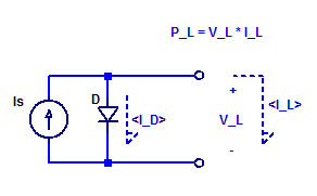
In this post, the maximum power point (MPP) of a diode shunted current source will be assessed and modeled. A solar cell in its simplest description is merely a semiconductor diode. When the cell’s junction is illuminated, a photo current \(Is\) is produced. A basic schematic model of an ideal solar cell is shown in the figure below.

Schematic of Diode Shunted Current Source.

For diode forward voltages \(V_D\) greater than a few \( \eta V_T\), such as 100 mV, the diode equation is approximately equal to,

$$ I_D \simeq I_o exp\left( \dfrac{V_D}{\eta V_T} \right) $$ Continue reading “Maximum Power Point of Diode Shunted Current Source”

Maximum Power Point of a Current Source

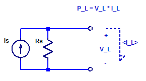
While it is true an ideal current source can deliver an infinite amount of output power (at a constant current), as the output compliance voltage is infinite. A real current source has a finite output resistance which limits the maximum output voltage that can be developed across the current source. To asses the peak output power of a current source, we will develop a relation for the output voltage as a function of load current. Consider the schematic of a current source connected to some arbitrary load \(V_L\) & \(I_L\).

Schematic of Current Source Power an Arbitrary Load.

Continue reading “Maximum Power Point of a Current Source”

Linearity of a DAC0800 Current Output R2R DAC

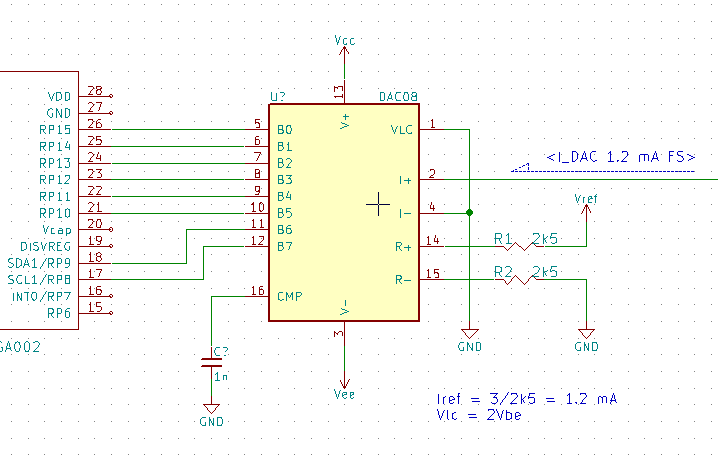
The DAC0800 is a current output R-2R DAC with 8 bits of resolution. As part of a solar panel monitor, the DAC0800 serves as a programmable reference for a shunt regulator. The output of the DAC is mirror 1:1 into a \(5\;k\Omega\) load; forming the voltage reference for the shunt regulator. A simplified schematic of the DAC is shown below.

Simplified schematic of a DAC0800.

Continue reading “Linearity of a DAC0800 Current Output R2R DAC”

NiCd Fast-Charge Profile

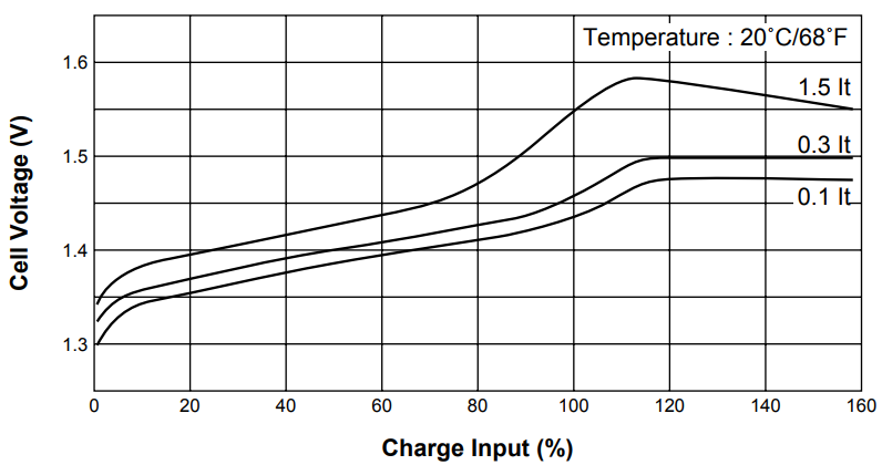
In this post, the charge profile of a Panasonic N-700AACL NiCd battery will be instrumented.

The two recommended termination signatures to be used when fast-charging NiCd cells are either negative \(\Delta V\) or positive dT/dt. Thermal detection is more challenging to implement as one requires good thermal contact between a temperature detector and the cell under charge. In the case of negative \(\Delta  V\) one already has the cell potential by the same contacts being used to apply the charge current. However, one requires sufficient measurement precision of the cell under charge to detect the relatively small  \( \Delta V\) signature.

The charge profile of an N-700 cell during various charge rates is shown in the figure below.

Datasheet example of the typical charge profile of a NiCd cell.

Continue reading “NiCd Fast-Charge Profile”

Trans-Impedance Amplifier – Transfer Function

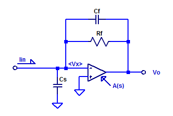
In this post, the current to voltage transfer function of a trans-impedance amplifier is derived. Consider a sample op-amp based trans-impedance amplifier as shown in the figure below.

Small-signal schematic of trans-impedance amplifier.

Capacitors \(C_f\) and \(C_s\) are included for completeness, as they do exist as parasitic elements in a real circuit. Parasitic shunt capacitance of \(R_f\) may be on the order of 100 fF. Capacitor \(C_s\) is the sum of routing capacitance (perhaps a few pF) and the input capacitance of the op-amp (perhaps 3 pF to 6 pF).

Continue reading “Trans-Impedance Amplifier – Transfer Function”