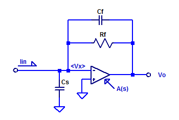
In this post, the current to voltage transfer function of a trans-impedance amplifier is derived. Consider a sample op-amp based trans-impedance amplifier as shown in the figure below.

Capacitors \(C_f\) and \(C_s\) are included for completeness, as they do exist as parasitic elements in a real circuit. Parasitic shunt capacitance of \(R_f\) may be on the order of 100 fF. Capacitor \(C_s\) is the sum of routing capacitance (perhaps a few pF) and the input capacitance of the op-amp (perhaps 3 pF to 6 pF).
Applying KCL at the inverting-input terminal of the op-amp yields,
$$ V_x s C_s + \dfrac{V_x -V_o}{R_f} +(V_x – V_o)sC_f = I_{in} $$
$$ V_x \left( sC_s + 1/R_f + sC_f \right) – V_o( 1/R_f + sC_f ) = I_{in} $$
$$ V_x \left( \dfrac{1 + sR_f(C_s + C_f) }{R_f}\right) – V_o( \dfrac{1 + sR_fC_f}{R_f} ) = I_{in} $$
The transfer function of the op-amp is modeled as a single pole, unity gain stable amplifier as,
$$ A(s) = \dfrac{A_{ol}}{1 – s/p_a} $$
Where \(A_{ol}\) is the DC open-loop gain and \(p_a\) is the pole based on the GBWP of the op-amp. Since the input signal is applied to the inverting terminal the gain is negative and equal to,
$$ V_o = – A(s) V_x $$
Rearrange for \(V_x\) as,
$$ V_x = \dfrac{-V_o}{A(s)} $$
Substitution into the KCL eqn as,
$$ \dfrac{-V_o}{A(s)} \left( \dfrac{1 + sR_f(C_s + C_f) }{R_f}\right) – V_o( \dfrac{1 + sR_fC_f}{R_f} ) = I_{in} $$
$$ \dfrac{-V_o}{A(s)R_f} \left( 1 + sR_f (C_s + C_f) + A(s) (1 +sR_fC_f)\right)= I_{in} $$
\begin{align*}
\dfrac{V_o}{I_{in}} &= \dfrac{-A(s)R_f}{ 1 + sR_f (C_s + C_f) + A(s) (1 +sR_fC_f)} \\ \\
&=\dfrac{-A_{ol}R_f}{ \left(1-s/p\right)\left(1 + sR_f (C_s + C_f) +\dfrac{ A_{ol}(1 +sR_fC_f)}{1-s/p} \right)} \\ \\
&=\dfrac{-A_{ol}R_f}{ 1 -s/p + sR_f(C_s+C_f)-\dfrac{s^2R_f(C_s+C_f)}{p_a} +A_{ol} +sA_{ol}R_fC_f} \\ \\
\dfrac{V_o}{I_{in}} &=\dfrac{-R_f}{ 1 + s\left( R_fC_f +\dfrac{R_f(C_s+C_f)}{A_{ol}} – \dfrac{1}{A_{ol}p_a}\right) -\dfrac{s^2R_f(C_s+C_f)}{A_{ol} p_a} } \\ \\
\end{align*}
Assuming the time-constant of \(R_fC_f\) is less than the GBWP of the opamp the transfer function can be approximated as,
$$ \dfrac{V_o}{I_{in}} \simeq \dfrac{-R_f}{ 1 + sR_fC_f -\dfrac{s^2R_f(C_s+C_f)}{A_{ol} p_a} } $$
If we assume the poles are well separated (atleast one decade in frequency) the dominant pole is then approximately,
$$ p_1 \simeq \dfrac{-1}{R_fC_f} $$
The second pole occurs at,
$$ p_2 \simeq \left( \dfrac{A_{ol}p_a}{R_f(C_s+C_f)} \right)\left( -R_fC_f \right) $$
Which is equivalently,
$$ p_2 = \dfrac{-\text{GBWP}}{2\pi}\left( \dfrac{C_f}{C_f + C_s} \right) $$
Spice Simulation
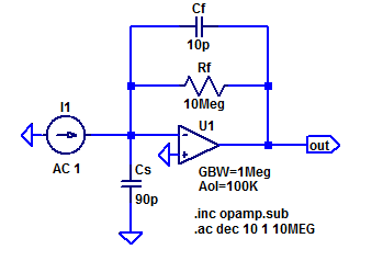
For the purposes of discussion, consider a prototype trans-impedance amplifier with the following parameters,
\begin{align*}
R_f &= 10 \text{ M}\Omega \\
C_f &= 10 \text{ pF} \\
C_s &= 90 \text{ pF} \\
A_{ol} &= 100 \text{ dB} \\
\text{GBWP} &= 1 \text{ MHz} \\
\end{align*}
The LT-Spice schematic of the sample amplifier is shown in the figure below.

The exact transfer function is then,
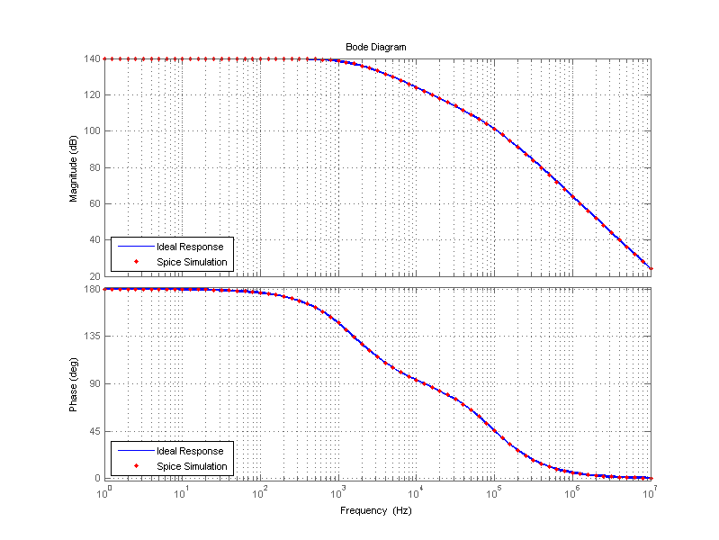
\[ \dfrac{V_{out}(s)}{I_{in}(s)}= H(s) = \dfrac{-10^7}{159.2\cdot 10^{-12} s^2 + 100.2\cdot 10^{-6} s + 1} \]
With the exact poles of \(H(s)\) being,
\[ p_1 = -1.615 \text{ [kHz]},\;\;\; p_2 = -98.554\text{ [kHz]}\]
The approximated poles as developed above are the following,
\[ \hat{p_1} = -1.592 \text{ [kHz]},\;\;\; \hat{p_2} = -100\text{ [kHz]}\]
A bode plot of the transfer function of this sample trans-impedance amplifier is shown in the figure below.
