All semi-conductor diodes have some amount of reverse-bias conductance. In the case of a 1N4148, reverse leakage current is guaranteed to be less than 25 nA when reverse-biased at -20 VDC at room temperature (25 degC). In this post we will measure the reverse biased I-V curve of 4 1N4148 diodes.
The standard spice model of a diode under reverse bias is the following,
\[
I_D =
\begin{cases}
I_s\left(e^{\eta qV_D/kT} -1 \right) + V_D\text{GMIN} &\quad\text{for} & -5\dfrac{\eta kT}{q} \leq V_D \leq 0 \\ \\
-I_s + V_D\text{GMIN} &\quad \text{for} & V_D < -5\dfrac{\eta kT}{q}\\
\end{cases}
\]
When the DUT is reverse biased from 0 mV to -250 mV, we expected to observe a large rise in leakage current. For reverse bias voltages less than -250 mV, we expect to see a constant current source with a high parallel resistance.
Measurement Setup
Various spice models provide the saturation current of a 1N4148 to be around 2 nA. Anticipating the leakage current will be on the order of 1 nA to 10 nA, we can choose a suitable current measurement technique. The minimum current measurement range of the 34401A multimeter is 10 mA. At 5-1/2 digit resolution (10 PLC) the current resolution 10 nA. At 6-1/2 digit resolution (100 PLC) the resolution is 1 nA. Neither of these modes are particularly attractive for a signal which is maximally 10 nA. If the 34401 was employed in DCI mode, a total of 10 ADC counts would be available.
Alternatively, we can use a current shunt resistor and measure the voltage developed across the current shunt resistor. Fortunately, the 34401A has the ability to provide a high input-resistance on its input terminals (Hi-Z mode). A schematic of the test setup is shown below,
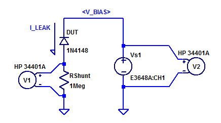
Here a 1 MOhm resistor is used as a current shunt resistor. Voltmeter V1 samples the potential across \(R_{shunt}\). Voltmeter V2 samples the bias potential being applied to the DUT. Power supply Vs1 is stepped programmaticly from 0 VDC to -20 VDC.
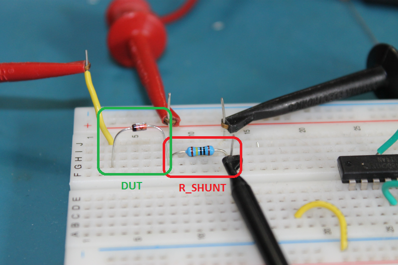
While a breadboard isn’t the ideal choice for low-level measurements, it is convenient for testing through-hole components. Test-jig leakages is assessed by applying a DC bias of 20 VDC to various nodes on the breadboard and recording shunt voltage. This leakage test, resulted in maximally 10 pA of leakage to the shunt resistor. For a first pass look at a 1N4148 with 1 nA of leakage, it will serve well for this blog post.
A photo of one DUT in the test setup is shown below.
Measurement Results
Room temperature and the shunt resistor are recorded as,
$$\begin{matrix}
T_{amb}\; : & 22.6 \; ^oC \\
R_{Shunt}\;: & 1.0009 \; M\Omega
\end{matrix}$$
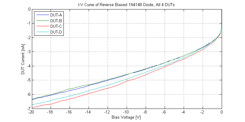
Each of the 4 1N4148 were reverse biased from 0 to – 20 VDC. The resulting leakage current can be seen in the figure below.
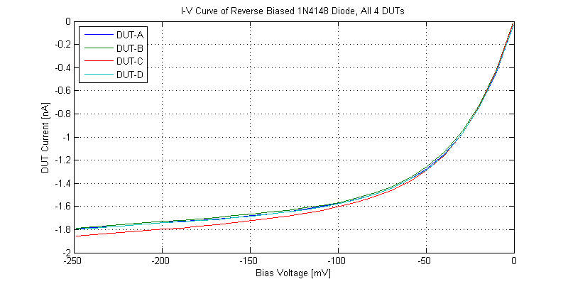
A figure with a reduced span of reverse bias voltages greater than – 250 mV is shown in the figure below.
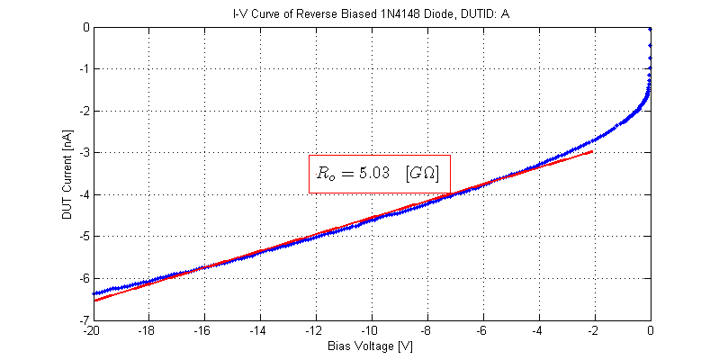
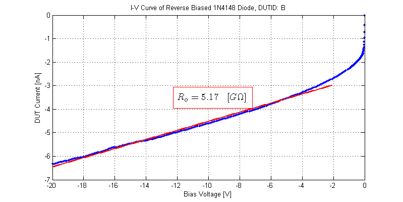
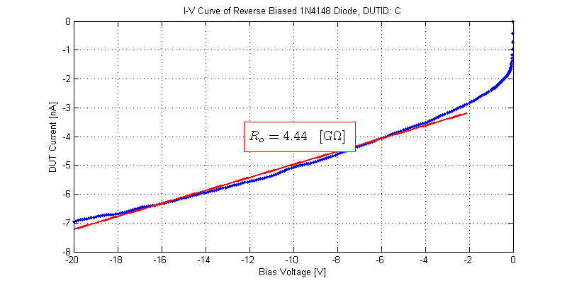
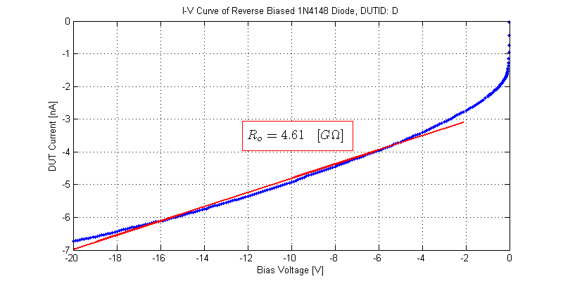
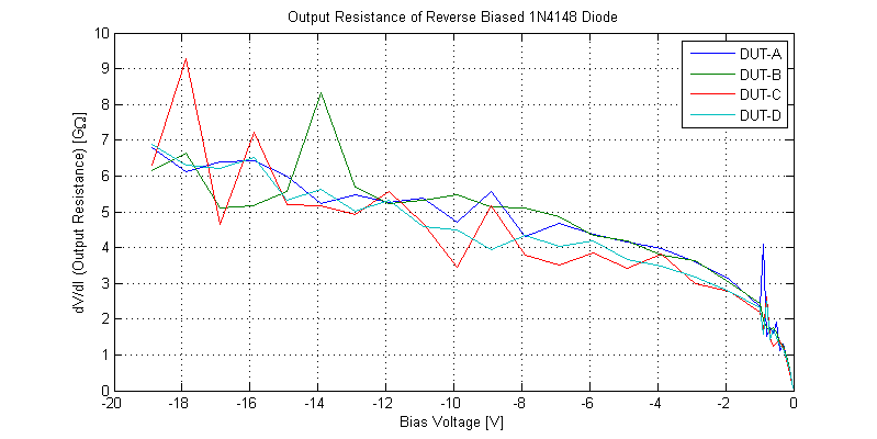
The blue excursion at approximately -1 VDC, is the 34401 range switching on the volts DC measurement of DUT reverse bias potential. Longer integration periods when measuring Rshunt would produce a cleaner plot (at the expense of test time).
By far the largest challenge in modelling these 4 sample 1N4148 diodes is the non-linear reverse bias conductance. Contrary to the spice model introduced above, these DUTs never reach a region of constant conductance. The piece-wise model defines the region of constant conductance as \(V_D \) < \(-5\eta V_T\). Assuming \(\eta \approx 2\), for reverse bias potentials less than -250 mV, the conductance should be constant. Even worse is that GMIN (conductance) is a global spice parameter not a unique component attribute. With GMIN having a typical default value of GMIN = \(10^{-12}\) mho, which is equivalently a shunt resistance of 1 TOhms.
Aside
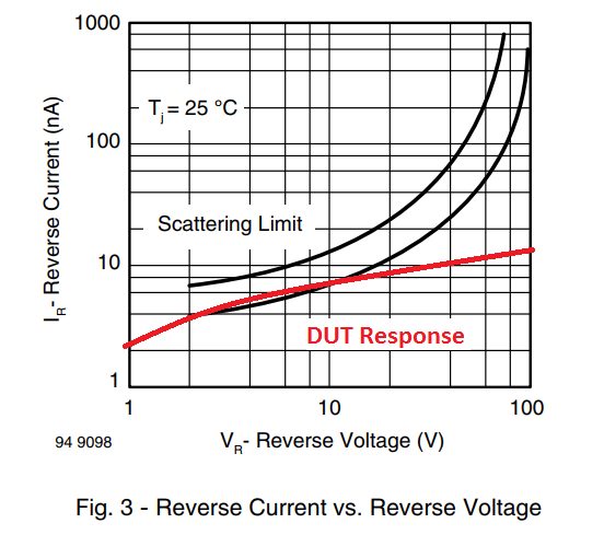
Even the typical response described in the datasheet is not observed on these 4 sample DUTs. A graph showing the typical reverse bias leakage taken from the following datasheet is shown below.
Raw Data
The I-V curves collected for the 4 DUTs can be found as csv files below:
– DUT A
– DUT B
– DUT C
– DUT D
Files are formatted as,
DUT Voltage [V], DUT Current [A]
Thanks for publishing your data! Doing a 2 minute timer/oscillator circuit with a small ceramic 4.7uF cap so needed a diode with very low leakage. Looks like the standard 1N4148 will work fine.
I recall a physics lesson where some very high value resistors were housed in a glass tube. The teacher used something (isopropyl alcohol?) to clean the tubes before using the resistors to remove grease which could otherwise bridge from one terminal to the other and reduce the resistance. Did you clean the diodes before doing the tests and if not, could this have biased the results much? I’m no expert, so my apologies if I am stating the obvious here.