1N4148 Reverse Breakdown Voltage

When a silicon diode is sufficiently reverse biased, the junction undergoes either avalanche or zener breakdown. Zener breakdown is a quantum mechanical behavior which typically occurs at potentials less than -5 V or -6 V for silicon diodes. Avalanche breakdown occurs when a thermally generated electron-hole pair is sufficiently accelerated by the reverse bias electrical field, such that, when they impact a second carrier they cause impact ionization. These additional free carriers then cause more impact ionization and this becomes a multiplicative process. Ultimately conducting high levels of current due to the multiplicative gains of avalanche breakdown.

Breakdown specifications taken from the 1N4148 datasheet are shown highlighted in the figure below.

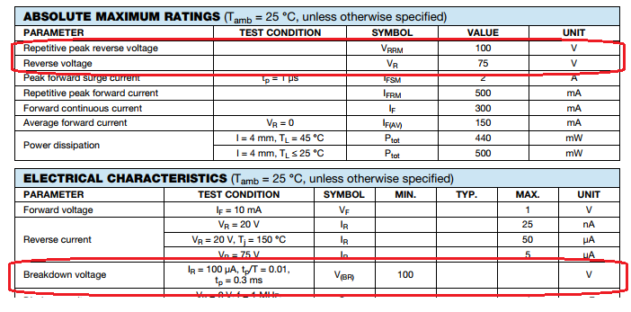
At room temperature, we expect to observe a breakdown voltage greater than 100 VDC. The recommended largest reverse working voltage is given as 75 VDC.

The standard spice model of a diode under reverse bias is the following,
\[
I_D =
\begin{cases}
I_s\left(e^{\eta qV_D/kT} -1 \right) + V_D\text{GMIN} &\quad\text{for} & -5\dfrac{\eta kT}{q} \leq V_D \leq 0 \\ \\
-I_s + V_D\text{GMIN} &\quad \text{for} & V_D < -5\dfrac{\eta kT}{q}\\ \\
-IBV & \quad \text{for} & V_D = -BV \\ \\
-I_S\left( e^{-q(BV+V_D)/kT}-1 + \dfrac{qBV}{kT}\right) & \quad \text{for} & V_D < – BV
\end{cases}
\]

Continue reading “1N4148 Reverse Breakdown Voltage”

1N4148 Reverse Bias Leakage Current

All semi-conductor diodes have some amount of reverse-bias conductance. In the case of a 1N4148, reverse leakage current is guaranteed to be less than 25 nA when reverse-biased at -20 VDC at room temperature (25 degC). In this post we will measure the reverse biased I-V curve of 4 1N4148 diodes.

The standard spice model of a diode under reverse bias is the following,
\[
I_D =
\begin{cases}
I_s\left(e^{\eta qV_D/kT} -1 \right) + V_D\text{GMIN} &\quad\text{for} & -5\dfrac{\eta kT}{q} \leq V_D \leq 0 \\ \\
-I_s + V_D\text{GMIN} &\quad \text{for} & V_D < -5\dfrac{\eta kT}{q}\\
\end{cases}
\]
When the DUT is reverse biased from 0 mV to -250 mV, we expected to observe a large rise in leakage current. For reverse bias voltages less than -250 mV, we expect to see a constant current source with a high parallel resistance.
Continue reading “1N4148 Reverse Bias Leakage Current”

Resistor I-V Linearity


One most likely doesn’t need any assistance in recalling Ohm’s law as,

$$ V = I R $$

Or equivalently,

$$ I = \dfrac{V}{R} $$

Of course this is an idealized expression, as all resistors have a voltage coefficient due to self-heating. A resistor R will dissipate a power under load of

$$ P_d = I^2 R $$

The power dissipation leads to a temperature rise and the temperature coefficient of resistance material leads to a deviation in nominal resistance.

In this blog post, we will take a look at the I-V linearity of a handful of 1 kOhm resistors. Continue reading “Resistor I-V Linearity”

Trans-conductance Amplifier Measurements

Continuing on from the analysis presented in low-noise-high-psrr-ldo-transconductance-gm-block, a simplistic trans-conductance amplifier can be constructed as shown in the figure below.

Schematic of Trans-conductance Amplifier

Forward trans-conductance from \( V_i \) to \( I_o \) was shown to be approximately,

$$ g_m = \dfrac{1}{R_E} \;\;\; \text{[A/V] } $$

For evaluation purposes, a \(g_m\) of 1 mA/V is chosen arbitrarily. The resistance of Re is then simply, Continue reading “Trans-conductance Amplifier Measurements”