A Digital to Analog Converter (DAC) in the ideal case, provides a unique transform from a digital code to an analog voltage ratiometric to a supplied voltage reference. Several codings of the digital value are available. Two of the simplest codings are unsigned binary and unsigned fractional binary. Other possible codings include: two’s complement, sign-magnitude, one’s complement, and gray code. In practice, only unsigned binary and two’s complement (signed binary) are commonly employed in a DAC. For both the signed and unsigned cases, the integer and fractional codings share the same binary representation. For example, a 3-bit DAC has the response shown in the table below.
| Decimal | Fractional | Unsigned Binary | Fractional Binary | DAC Output |
|---|---|---|---|---|
| 0 | 0/8 | 000 | 0.000 | \( 0/8 \; V_{REF} \) |
| 1 | 1/8 | 001 | 0.001 | \( 1/8 \; V_{REF} \) |
| 2 | 2/8 | 010 | 0.010 | \( 2/8 \; V_{REF} \) |
| 3 | 3/8 | 011 | 0.011 | \( 3/8 \; V_{REF} \) |
| 4 | 4/8 | 100 | 0.100 | \( 4/8 \; V_{REF} \) |
| 5 | 5/8 | 101 | 0.101 | \( 5/8 \; V_{REF} \) |
| 6 | 6/8 | 110 | 0.110 | \( 6/8 \; V_{REF} \) |
| 7 | 7/8 | 111 | 0.111 | \( 7/8 \; V_{REF} \) |
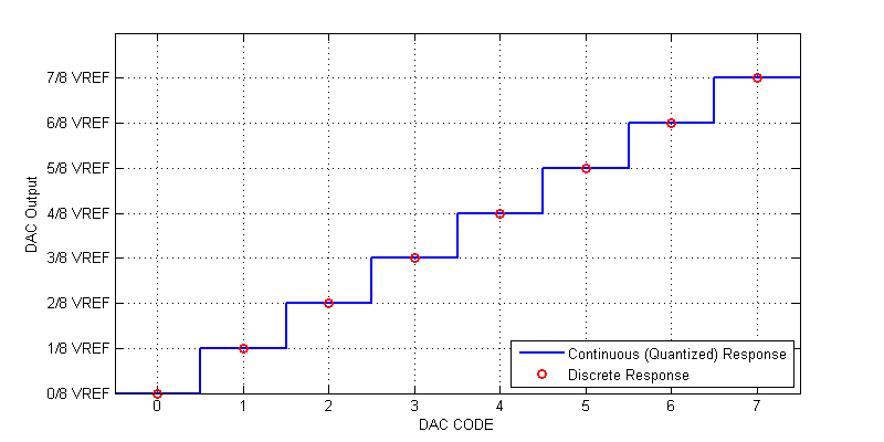
In the ideal case, for any input DAC code, the output is exactly equal to the fractional value relative to its associated voltage reference. For example, a 3-bit DAC has response to DAC code 4 (0b100) of exactly \(1/2\; V_{REF}\). The complete response of an ideal 3-bit DAC is shown in the figure below.

We can see that at each exact DAC code, the response has no error, i.e the response is ideal. However, if we wished to output a value of \(1/16 V_{REF}\) we have only two choices, either \( 0 \) V or \( 1/8 \; V_{REF} \). Neither of these two codes provide the response we desire. Any DAC will ALWAYS round to the closest integer code, thus inuring an error of up to \(\pm 1/2 \text{ LSB}\) within full-scale. When we translate a higher resolution value (bits or fraction) to a lower resolution value, we describe this loss of fidelity as quantization.
Quantization Noise
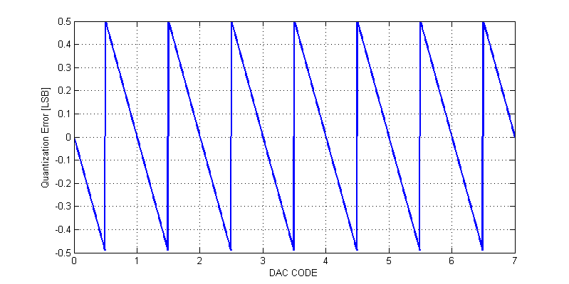
Since a DAC has only \( 2^n\) possible output values, we do not have infinite set of possible output values. As a result we must always round an output value to the nearest DAC code. When the output is rounded we incur round-off error or quantization error. As an example the quantization error of 3-bit DAC is shown in the figure below.

Quantizaiton is also inherently a lossy and thus non-linear process. When a DAC outputs code 0, we have no knowledge whether the intended value was less than 0 or between 0 and 0.5 LSB. All we can observe is that the output is 0.
The error introduced due quantization can be assessed from a statistical viewpoint or simply as an RMS quantity. While the statistical viewpoint is the “correct” approach, the results from an RMS treatment, turn out to be the same. For the sake of discussion, we will treat the quantiation error as a voltage noise source with some RMS magnitude. We can observe that the quatization error is periodic, with a periodicity of one code value. The RMS value of a periodic function is the following
\[ V_{rms} = \sqrt{ \dfrac{1}{T} \int_0^T f(t)^2 dt } \]
The quantization error over the span -1/2 LSB to + 1/2 LSB, can be described as the following function
\[ f(x) = -x \Delta \]
The periodicity of the quantization is one code, i.e. T = 1. The rms error due to quantization is then,
\begin{align*}
V_{n,rms} &= \sqrt{ \dfrac{1}{T} \int_{-1/2}^{+1/2} f(x)^2 dx } \\
&= \sqrt{ (1) \int_{-1/2}^{+1/2} \Delta^2 x^2 dx } \\
&= \sqrt{ \left[ \dfrac{\Delta^2}{3\cdot 8} + \dfrac{\Delta^2}{3\cdot 8} \right] } \\
V_{n,rms} &= \dfrac{\Delta}{\sqrt{12}}
\end{align*}
Signal to Quantization Noise
When a DAC is synthesizing a full scale sinusoidal waveform, the peak-peak amplitude spans from 0 V to a maximum of \( V_{REF} \). The RMS of a full-scale sinusoidal waveform is,
\[ V_{rms} = \dfrac{ V_{AMPLITUDE} }{\sqrt{2}} \]
Thus the full-scale signal has an RMS magnitude of
\[ V_{s,rms} = \dfrac{ V_{REF}/2 }{\sqrt{2}} \]
Signal to Noise Ratio (SNR) is historically defined as the power ratio of signal to noise. Here will apply the amplitude ratio and apply a 20log scale (equivalent to using a 10log scale and squaring the amplitude).
\begin{align*}
\text{SNR} &= 20\log \left( \dfrac{V_{s,rms}}{V_{n,rms}} \right) \\ \\
\text{SNR} &= 20\log \left( \dfrac{ \dfrac{ V_{REF}/2 }{\sqrt{2}} }{\dfrac{\Delta}{\sqrt{12}}} \right) \\
\text{SNR} &= 20\log \left( \dfrac{V_{REF} \sqrt{12} }{\Delta 2\sqrt{2} }\right) \\
\text{SNR} &= 20\log \left( \dfrac{ \sqrt{12} }{ 2\sqrt{2} }\right) + 20\log\left( \dfrac{V_{REF}}{\Delta}\right) \\
\end{align*}
Recall that,
\[ \Delta = \dfrac{V_{REF}}{2^n} \]
Thus the signal to quantization noise ratio becomes,
\begin{align*}
\text{SNR} &= 1.76 + 20\log\left( 2^n \right) \\ \\
\text{SNR} &= 1.76 + 6.02n \text{ [dB]} \\
\end{align*}
We then see the infamous signal to quantization noise ratio commonly applied to data converters. Each additional bit added to a data converter provides a 6 dB improvement in SNR (double amplitude, quadruple power).