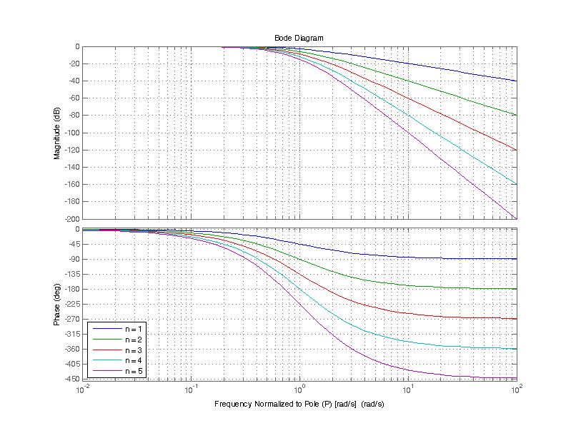
One approach to improving stopband rejection is to cascade several first-order filters, there by achieving the combined rejection of n filters for better stopband rejection. While the implantation of such an arrangement is straight forward, there are some consequences to this approach which will be discussed below.
For a low-pass filter of the form
\[ H(s) = \dfrac{1}{1 + s/p} \]
From control theory the cascaded transfer function is just the multiplication of each filter transform. When each filter has an identical transfer function the overall transfer function is the following
\[ C(s) = \dfrac{1}{(1 + s/p)^n} \]
The poles of C(s) are easy to compute, as there are n identical roots of the denominator at s = -p. C(s) has n poles at
\[ p_1 = p_2 = … = p_n = -p \]
Applying the binomial theorem to the denominator yields
\[ C(s) = \dfrac{1}{1 + {n\choose 1}\left( \dfrac{s}{p} \right) + {n\choose 2}\left( \dfrac{s}{p} \right)^2 +…+ {n\choose n}\left( \dfrac{s}{p} \right)^n } \]
From the expansion of C(s) the first major draw back can be seen that the first s term is multiplied by n, which results in moving the -3 dB point from fc to towards DC.
| Normalized Frequency (w/p) | n=1 Magnitude (dB) | n=2 Magnitude (dB) | n=3 Magnitude (dB) | n=4 Magnitude (dB) | n=5 Magnitude (dB) |
|---|---|---|---|---|---|
| 0.01 | -0.0 | -0.0 | -0.0 | -0.0 | -0.0 |
| 0.1 | -0.0 | -0.1 | -0.1 | -0.2 | -0.2 |
| 1 | -3.0 | -6.0 | -9.0 | -12.0 | -15.1 |
| 10 | -20.0 | -40.1 | -60.1 | -80.2 | -100.2 |
| 100 | -40.0 | -80.0 | -120.0 | -160.0 | -200 |
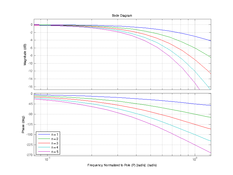
A bode plot of the combined transfer function for 1 to 5 cascaded single pole filters is shown below.

Note that the -3 dB attenuation at \( \omega_c \) is cumulative for n cascaded poles, i.e. for n=5 the attenuation at \( \omega_c \) is -15 dB.

Consequently, the effective bandwidth as defined by the -3 dB point decreases for an increasing number of cascaded single pole filters. The effective bandwidth when 1 to 5 single pole filters are cascaded is shown in the table below.
| Number of Filters | Bandwidth |
|---|---|
| 1 | fc |
| 2 | 0.64*fc |
| 3 | 0.51*fc |
| 4 | 0.43*fc |
| 5 | 0.38*fc |
In the case of cascading 5 single pole filters, one could instead use 5 filters with a corner frequency 2.63*fc, where fc is the desired -3 dB corner frequency. However the attenuation in the first frequency decade of the stopband is not simple n times the single pole case. The table below shows the filter attenuation, for the frequency one decade past the -3 dB point.
| Number of Filters | -3 dB Frequency | One decade advanced in frequency | Attenuation [dB] |
|---|---|---|---|
| 1 | fc | 10*fc | -20 |
| 2 | 0.64*fc | 6.4*fc | -32 |
| 3 | 0.51*fc | 5.1*fc | -43 |
| 4 | 0.43*fc | 4.3*fc | -52 |
| 5 | 0.38*fc | 3.8*fc | -59 |