In a traditional oscillator, oscillation is achieved by providing a loop-gain greater than unity and a phase-shift of \(0^o\) at some \(f_{osc}\). However, in the case of a relaxation oscillator, oscillation is achieved by switching between two discrete states. Often a relaxation oscillator is constructed with a non-linear circuit element which can provide 2 threshold voltage levels to define two discrete states. One non-linear circuit element which is commonly employed in a relaxation oscillator is a schmitt trigger.
Due to the hysteresis developed internal to the schmitt trigger, two trigger thresholds are realized, namely \(V_N\) and \(V_P\). Where \(V_N\) is the negative threshold voltage and \(V_P\) is the positive threshold voltage. The hysteresis voltage is then,
$$ V_H = V_P – V_N $$
Ideally, the thresholds \(V_N\) and \(V_P\) would be centered around mid-supply (\(V_{dd}/2\)), however in practice this is only approximately true.
A minimal component count relaxation oscillator is shown in the figure below.

Due to the high-gain and hysteresis of a schmitt trigger only two output values are obtained; Vdd for output-high and Ground for output-low. Feedback resistor \(R\) controls the charge/discharge current of capacitor \(C\).
Simplified Theory of Operation
If we consider the hysteresis voltage \(V_H\) to be small compared to the supply voltage \(V_{dd}\), then during oscillation, the voltage of capacitor C is approximately \(V_{dd}/2\). By approximating V(C), we can simplify the charge current to be approximately,
$$ I_{chg} =\dfrac{V_{oh} – V_C}{R} = \dfrac{V_{dd} – V_{dd}/2}{R} $$
Equivalently, the discharge current is,
$$ I_{dis} =\dfrac{V_C – V_{ol}}{R} = \dfrac{ V_{dd}/2 – 0}{R} $$
Since the average voltage of capacitor C is \(V_{dd}/2\) the charge/discharge currents are symmetric and equal.
$$ I_{chg} = I_{dis} =\dfrac{ V_{dd}}{2R} $$
We can analyze the two discrete states independently to determine the period of oscillation. A simplified schematic and state model of the oscillator is shown in the figure below.
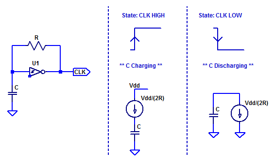
When the output transitions high the capacitor begins charging. Since we assumed \(V_H\) to be small compared to \(V_{dd}\) the current is approximately constant. Hence, we can simplify R as a constant current source.
When power to the circuit is initially applied, the capacitor is completely discharged. Since U1 is inverting, its output is high and capacitor C begins charging. The figure below summarizes the sequence of events that occur during oscillation.
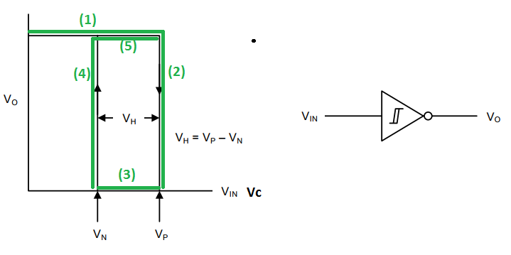
(1) Start-up, capacitor C begins charging until its value reaches the the threshold voltage \(V_P\).
(2) With V(c) greater than \(V_P\) the output transitions low, hysteresis internal to the schmitt trigger shifts the threshold to \(V_N\).
(3) With the output low, capacitor C begins discharging.
(4) Capacitor C discharges below threshold voltage \(V_N\) causing the output to transition high. Hysteresis internal to the schmitt trigger shifts the threshold voltage to \(V_P\)
(5) Capacitor C begins charging.
(…) Process repeats indefinitely.
Period of Oscillation – Simple Model
For the simplified model of the relaxation oscillator, we can determine the period of oscillation based on the charge equation of a capacitor,
$$ Q = CV $$
For the charging case we know the capacitor must charge from \(V_N\) to \( V_P\), a total voltage of \(V_H\). We can solve the charge required as,
$$ \Delta Q = C V_H $$
The time needed to accumulate \(\Delta Q\) coulombs of charge on capacitor C is then,
$$ \Delta t = \dfrac{ \Delta Q}{ I_{chg} } $$
Since the charge/discharge currents are equal the charge/discharge periods are then,
$$ t_{chg} = \dfrac{CV_h}{I_{chg}},\;\;\;t_{dis} = \dfrac{CV_h}{I_{dis}} $$
From the assumptions above of small \(V_H\) at mid-supply the charge/discharge current is,
$$ I_{chg} \simeq I_{dis} = \dfrac{V_{dd}/2}{R} $$
Finally, the total period of oscillation is then,
$$ T_{osc} = t_{chg} + t_{dis} = 4 RC \dfrac{ V_h}{V_{dd}} $$
Equivalently, the frequency of oscillation is,
$$ f_{osc} = 1/T_{osc} = \dfrac{ V_{dd}}{4RCV_h} $$
As an example consider the following relaxation oscillator,
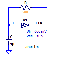
The period of oscillation for the sample circuit above is then approximately,
$$ T_{osc} = 4 (500 \; \Omega)( 1\; \mu\text{F} )\left( \dfrac{ 0.5\;\text{V}}{10\;\text{V}}\right) = 100 \; \mu\text{s} $$
A spice transient simulation of the sample oscillator is shown in the figure below.
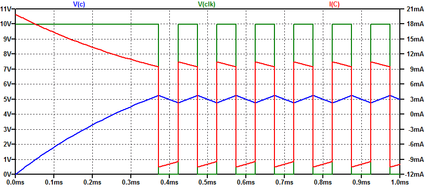
After start-up the period of oscillation is approximately 100 \(\mu s\). The charge/discharge current is not constant, but rather, it varies from 9.5 mA to 10.5 mA over a charge/discharge cycle.
Period of Oscillation – Complex Model
Instead of assuming the charge/discharge current is constant and symmetric we can instead analyze the period of oscillation based on the step response of an RC circuit. The figure below depicts several RC charge/discharge cycles transitioning through threshold voltages \(V_N\) and \(V_P\).
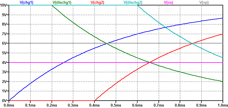
The general solution for the step response of an RC circuit is the following,
$$ V_C(t) = V_C(0) + \left( V_C(\infty) – V_C(0) \right)\left( 1 – e^{-t/\tau} \right) $$
Charge Time
During the capacitor charging cycle, the capacitor begins with a \voltage (V_N\) and terminates charging at voltage \(V_P\). If the charge cycle was not terminated (i.e. not oscillating) the steady-state value would reach power supply voltage \(V_{dd}\). Thus we have the following boundary conditions,
$$ V_C(0) = V_P, \;\;\; V_C(\infty) = V_{dd} $$
Substituting the boundary conditions for the charge cycle into the general solution yields,
$$ V_C(t) = V_N + \left( V_{dd} – V_N \right)\left( 1 – e^{-t/\tau} \right) $$
Where,
$$ \tau = RC $$
is the RC time-constant of the circuit.
We can solve for the charge time by solving for when for when the capacitor reaches a potential of \(V_P\) as,
\begin{align*}
V_C(t_c) &= V_P \\
V_P &= V_N + \left( V_{dd} – V_N \right)\left( 1 – e^{-t_c/\tau} \right)\\
V_P – V_N – V_{dd} + V_N &= \left( V_{dd} – V_N \right)\left( – e^{-t_c/\tau} \right)\\
\dfrac{ V_{dd} – V_P }{V_{dd} – V_N } &= e^{-t_c/\tau} \\
\log \left( \dfrac{ V_{dd} – V_P }{V_{dd} – V_N } \right) &= \dfrac{-t_c}{\tau}
\end{align*}
Finally, the time duration of the charge cycle is,
$$ t_c = \tau \log\left( \dfrac{V_{dd} – V_N }{ V_{dd} – V_P } \right) $$
Discharge Time
During the discharge cycle the capacitor discharges from threshold voltage \(V_P\) to threshold voltage \(V_N\). If the capacitor was left to fully discharge the final steady-state value would be 0 VDC. With boundary conditions,
$$ V_C(0) = V_P, \;\;\; V_C(\infty) = 0 $$
Substituting the boundary conditions into the general solution yields,
\begin{align*}
V_C(t) &= V_P + \left( 0 – V_P \right)\left( 1 – e^{-t/\tau} \right) \\
V_C(t) &= V_P \left( e^{-t/\tau} \right)
\end{align*}
Solving for when the capacitor discharges to potential \( V_N\),
\begin{align*}
V_C(t_d) &= V_N \\
V_N &= V_P \left( e^{-t_d/\tau} \right) \\
\log \left( \dfrac{V_N}{V_P} \right) &= \dfrac{-t_d}{\tau}
\end{align*}
The time duration for the discharge cycle is then,
$$ t_d = \tau \log \left( \dfrac{V_P}{V_N} \right) $$
Period of Oscillation
Knowing the time duration of both the charge and discharge cycles, the period of oscillation is then,
$$ T = t_c + t_d = \tau \log\left( \dfrac{V_{dd} – V_N }{ V_{dd} – V_P } \right) + \tau \log \left( \dfrac{V_P}{V_N} \right) $$
After some algebra, the final solution is,
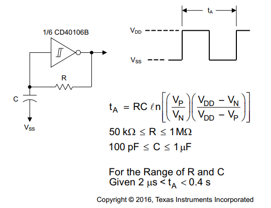
$$ T = RC \log\left( \dfrac{ \left(V_{dd} – V_N\right)V_P }{ \left(V_{dd} – V_P\right)V_N } \right) $$
Which is identical to the solution presented in the CD40106 datasheet, as shown in the figure below.
1 thought on “CD40106 Schmitt Trigger Relaxation Oscillator”