Physical synthesis of a Butterworth filter requires components which can be interconnected to form complex poles (dampened harmonic oscillators). A passive arrangement of resistors and capacitors can form arbitrary real valued poles and zeros; however a passive RC network cannot synthesize complex poles. The natural choice for passive components which can synthesize oscillators, are inductors and capacitors. An immediate benefit of choosing an LC network for synthesis, is that the network in the ideal case is lossless. Allowing for low insertion-loss in the pass-band, and maximizing power transfer from source to load.
The most common network structure for synthesis is a series inductor and shunt capacitor ladder. A LC ladder of arbitrary order \(n\), is shown in the figure below.

How poles (real or complex) are mapped to the component values in an LC ladder will be covered in a separate post titled “LC Ladder – Network Synthesis“.
For a restively terminated LC ladder with matched source and load resistance, the component values for the prototype case can be calculated as follows
\[ A_k = 2 \sin \left( \dfrac{(2k-1)\pi}{2n}\right)\;;\;\;\; k = 1,2,…,n \]
Tabulated component values for prototype filters with 1 to 8 components is given in the table below
| - | L1 | C2 | L3 | C4 | L5 | C6 | L7 | C8 |
|---|---|---|---|---|---|---|---|---|
| 2 | 1.4142 | 1.4142 | ||||||
| 3 | 1.0000 | 2.0000 | 1.0000 | |||||
| 4 | 0.7654 | 1.8478 | 1.8478 | 0.7654 | ||||
| 5 | 0.6180 | 1.6180 | 2.0000 | 1.6180 | 0.6180 | |||
| 6 | 0.5176 | 1.4142 | 1.9319 | 1.9319 | 1.4142 | 0.5176 | ||
| 7 | 0.4450 | 1.2470 | 1.8019 | 2.0000 | 1.8019 | 1.2470 | 0.4450 | |
| 8 | 0.3902 | 1.1111 | 1.6629 | 1.9616 | 1.9616 | 1.6629 | 1.1111 | 0.3902 |
Alternate LC Ladder Order
An equivalent LC ladder to that of the one introduced above is shown in the figure below.
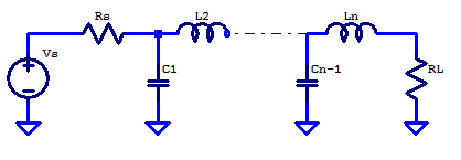
Note the component order and numbering, in this case the ladder begins with capacitor \(C_1\). Interestingly, the component values for both ladder structures are equivalent for on a index basis, i.e., the first component whether that be a series inductor or shunt capacitor have the same tabulated value.
Tabulated component values are shown in the table below. Its worth noting that the two table are identical on a component index basis. The second table is redundant and only shown for completeness.
| - | C1 | L2 | C3 | L4 | C5 | L6 | C7 | L8 |
|---|---|---|---|---|---|---|---|---|
| 2 | 1.4142 | 1.4142 | ||||||
| 3 | 1.0000 | 2.0000 | 1.0000 | |||||
| 4 | 0.7654 | 1.8478 | 1.8478 | 0.7654 | ||||
| 5 | 0.6180 | 1.6180 | 2.0000 | 1.6180 | 0.6180 | |||
| 6 | 0.5176 | 1.4142 | 1.9319 | 1.9319 | 1.4142 | 0.5176 | ||
| 7 | 0.4450 | 1.2470 | 1.8019 | 2.0000 | 1.8019 | 1.2470 | 0.4450 | |
| 8 | 0.3902 | 1.1111 | 1.6629 | 1.9616 | 1.9616 | 1.6629 | 1.1111 | 0.3902 |
| - | L1 | C2 | L3 | C4 | L5 | C6 | L7 | C8 |
Translating Prototype Filter to Arbitrary \(R_L\) & \( f_c \)
The filter components can be translated to a new corner frequency \( f_c \) and load resistance \(R_L\) by the following relations. Recall for the prototype case \(\omega_p = 1\) and \(R_P =1 \).
\begin{align*}
C_n’ &= C_{n} \left( \dfrac{\omega_p}{\omega_c} \right) \left( \dfrac{R_P}{R_L} \right) \\
C_n’ &= \dfrac{C_n}{2\pi f_c R_L }
\end{align*}
\begin{align*}
L_n’ &= L_{n} \left( \dfrac{\omega_p}{\omega_c} \right) \left( \dfrac{R_L}{R_P} \right) \\
L_n’ &= \dfrac{L_{n}R_L}{2\pi f_c }
\end{align*}
Where \( C_n’ \) and \( L_n’ \) are the translated component values.
Example: 5th Order Prototype
As an example a 5th order prototype butter worth will be constructed. For comparison both ladder structures will be included. The figure below shows both ladder structures.
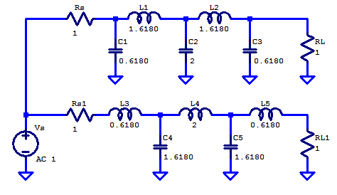
Its worth noting that a ladder with 5 components, provides a 5th order filter with 100 dB/decade attenuation in the stop-band.
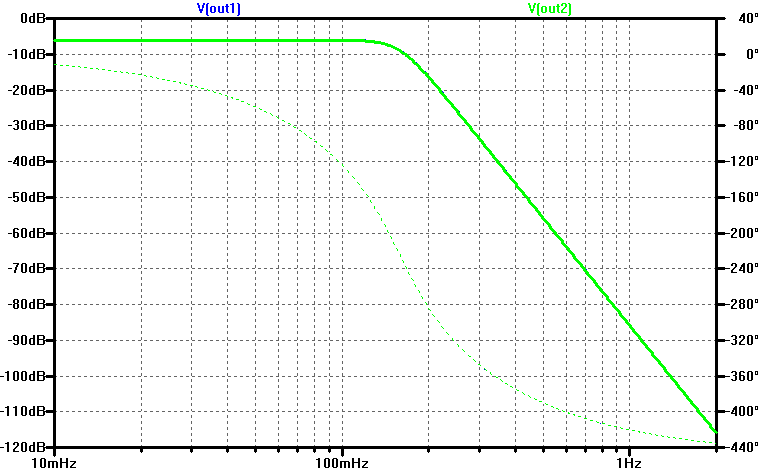
A bode plot of both ladder structures is shown below. As expected, both ladder forms provide identical transfer functions.
The input impedance of both filters is simulated with the addition of test current sources \(I_1, I_2\).
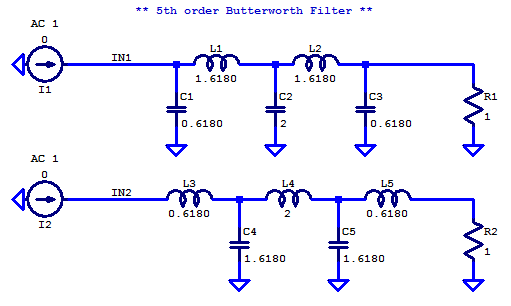
The input impedance of both ladder structures is shown below in dBOhms. In the pass-band the input impedance is \(R_L\). In the stop-band the input impedance is dominated by the first ladder element either an inductor or capacitor. A resonance mode is also visible for both filters. In the case of the ladder 1, beginning with a capacitor, it is parallel resonant and tends to a high impedance. In the second case, where the ladder begins with an inductor, the inductor is series resonant and tends to a low-impedance at resonance.
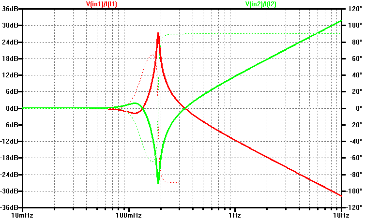
The output impedance of the ladder is simulated with a test currents \( I_1\) and \(I_2 \), one for each ladder.
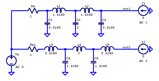
The output impedance as a function of frequency is plotted below in dBOhms.
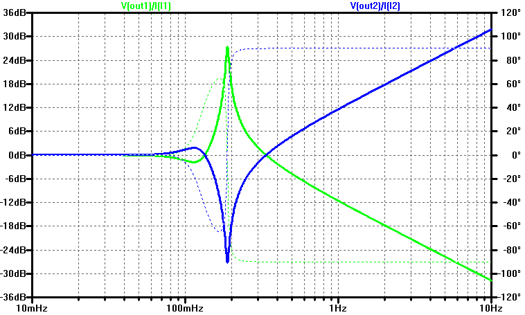
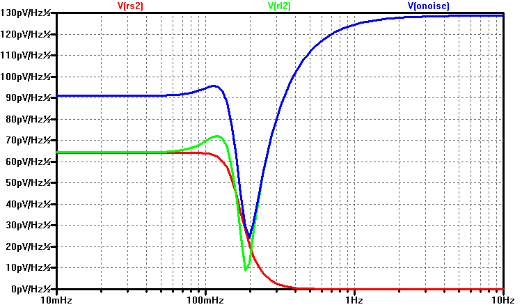
Since the LC ladder is lossless, it is also conveniently noiseless. The figure below shows the output refereed noise for the ladder beginning and terminating with a capacitor. 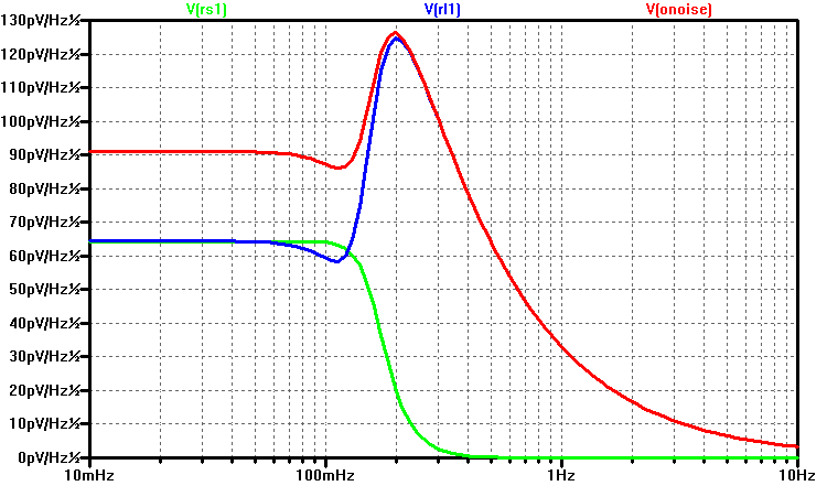
The spectral amplitude-noise of a 1 Ohm resistor at 300 K is the following
\begin{align*}
Sn &= \sqrt{4kTR} \\
Sn &= \sqrt{4(1.38\text{E-23})(300)(1) } \\
Sn &= 129 \text{ pV/rtHz} \\
\end{align*}
At the resonant frequency, which occurs at the beginning of filter’s stop-band, the output refereed noise peaks to a value equal the noise of \(R_L\).
For the alternate ladder structure, the output referred noise is shown below
