General Case
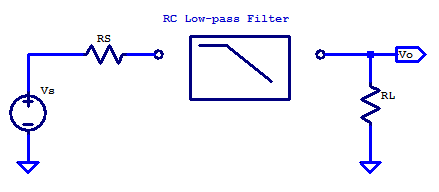
For the general case of applying a filter between some signal source and load point, the solution space is constrained when the design is limited to only resistors and capacitors. For the sake of discussion, consider the schematic below. Here the signal source \(V_S\) has an output resistance of \(R_S\) and the filter is loaded by the input input resistance of the proceeding signal stage.

In some cases, the load resistance is negligible. For example the non-inverting input of an op-amp, when configured as a unity gain buffer has very high input resistance and only a small shunt capacitance. The output resistance of an 0p-amp, when operating closed-loop with negative feedback, is also a relatively low output resistance signal source. Other cases which have significant source resistance include a plethora of transducers, such as the electret condenser in a microphone. A load with significant input resistance is a loudspeaker, which provides a load resistance ranging from 4 ohms to 32 ohms.
In the general case, additional resistance in the signal path is often undesirable, as it limits the power transfer capability from source to load. Additional resistance whether it be in series or parallel to the load, yeilds additional signal attenuation from source to load, there by lowering the filtered signal level, which in turns degrades the Signal to Noise Ratio (SNR).
When the source resistance is significant, only an additional capacitor is required.
Idealized Case
The idealized case is when the source resistance is low, and load resistance is high.
\[R_S = 0, \;\;\; R_L = \infty \]
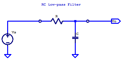
Under these source and load conditions, a common implementation of an RC low-pass filter is shown in the figure below

Generalized Theory of Operation
In the idealized case, the RC low-pass filter has two passive components, namely, a resistor and a capacitor. The series resistor \(R\) is an ideal resistor (not a high-frequency lumped element RLC model), which has a constant resistance across the frequency spectrum. The shunt capacitor \(C\) has an impedance which decreases with increasing frequency. Low-pass filtering occurs due to the declining impedance of the capacitor with frequency, which progressively shunts more and more current to ground as frequency increases. Ultimately as the signal frequency continues to increases, capacitor C, appears as a short to ground.
Analytical Theory of Operation
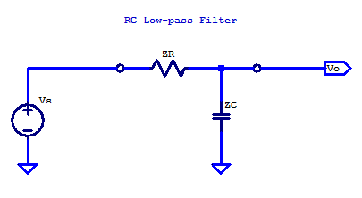
The easiest solution for the transfer function of \( V_O/V_S \) is realized treating the RC network as a voltage divider. Substituting the component designators R and C for their impedance \(Z_R\) and \( Z_C\) respectively is shown on the figure below.

\[ Z_R = R\]
\[ Z_C = \dfrac{1}{sC} \]
The circuit can then be conveniently analyzed as a voltage divider, which yields the standard voltage divider relation as
\[ V_O = V_S \left( \dfrac{Z_C}{Z_R + Z_C} \right) \]
The transfer function is then simply
\[ H(s) = \dfrac{V_O(s)}{ V_S (s)} = \left( \dfrac{Z_C}{Z_R + Z_C} \right) \]
Substituting the impedance values for \(Z_R\) and \( Z_C\) yields
\begin{align*}
H(s) &= \dfrac{\frac{1}{sC}}{R + \frac{1}{sC} } \\
H(s) &= \dfrac{1}{1 + sRC} \\
\end{align*}
H(s) is a unity gain, single pole transfer function, with its pole at
\[ p = \dfrac{-1}{RC} \]
The -3 dB corner frequency is
\[ \omega_c = -p \]
\begin{align*}
f_c &= \dfrac{\omega_c}{2\pi} \\
f_c &= \dfrac{1}{2\pi R C} \\
\end{align*}
A detailed evaluation of a single pole transfer function can be found here: Single Pole Transfer Function
Note to self, add bode plot at the end.